
The 555 timer has gained a legendary reputation as an integrated circuit (IC) since its emergence in the 1970s, with hobbyists, students, and professional engineers alike rating it highly for its affordability, ease of use, and versatility.
For projects ranging from simple LED flashers to complex signal generators, the 555 timer IC has shown time and time again why it is a go-to component.
If, however, you are interested in building oscillators and pulse generators using the 555 timer, there is another tool that will greatly support you in such endeavours: a dedicated 555 timer calculator. You can find these calculators in various places online, including the website of the electrical component supplier, RS.
With the right calculator bookmarked, you can quickly and easily calculate 555 timer values for both monostable and astable configurations. This, in turn, can help bring greater speed and ease to your projects in general.
So, let’s look at the key steps of performing such calculations.
A Brief Introduction to the 555 Timer IC
The 555 timer is a highly stable IC that can produce accurate time delays or oscillations.
This device is available in through-hole and surface-mount packages from various UK suppliers, such as the aforementioned RS. It is easy to obtain and inexpensive, often priced at less than £1.
There are three modes that the chip can operate in:
- Monostable mode, which produces a single pulse of a set duration
- A stable mode, which generates a continuous square wave (oscillator)
- Bistable mode, which acts as a simple flip-flop.
For the purposes of this article on the building of oscillators and pulse generators, we will focus on the astable and monostable modes, respectively.
These circuits would not work in the absence of the right resistors and capacitors. Sure enough, the 555 timer calculator will help you make the appropriate selections with your projects.
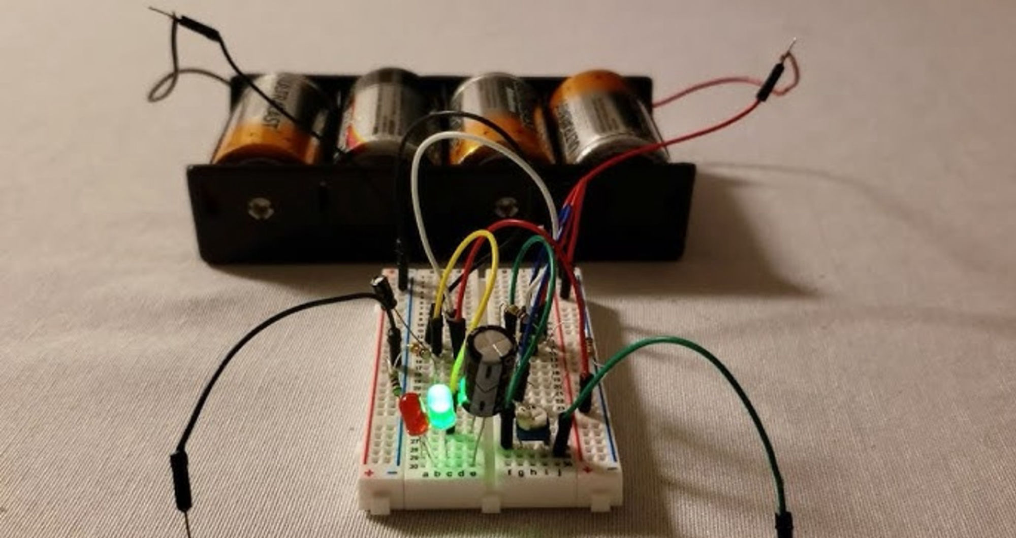
Astable Mode: Building An Oscillator
When the 555 timer IC is in astable mode, it produces a continuous square wave. This lends itself well to such applications as LED flashers, tone generators, and clock signals.
The output oscillates between high (Vcc) and low (OV). The frequency and duty cycle of the pulses are determined by two resistors (R1, R2) and a capacitor (C).
The key formulas for this 555 timer mode are as follows:
- Frequency (f): f = 1.44 / ((R1 + 2R2)C), where f is in hertz, R1 and R2 are in ohms, and C is in farads
- Time high (Th): Th = 0.693(R1 + R2)C
- Time low (Tl): Tl = 0.693R2C
- Duty cycle: Th / (Th + Tl) x 100%.
These formulas can, of course, be used for manual workings-out… or you may prefer to turn to the 555 timer calculator.
In the latter case, by entering the values for R1, R2, and C into the calculator fields and pressing the “Calculate” button, you can be presented with the resulting frequency, as well as the time high and time low.
Monostable Mode: Building A Pulse Generator
This mode of a 555 timer IC generates a single pulse when triggered. This makes it a suitable mode for timers, debouncing switches, or pulse-width modulation (PWM).
The output pulse’s length is determined by a single resistor (R) and a single capacitor (C).
The key formula here, then, is for pulse duration (t): t = 1.1 x R x C, where t is in seconds, R is in ohms, and C is in farads.
Using a 555 timer calculator for this process, then, can be as simple as entering the values for R and C, and clicking the “Calculate” button, to generate a result for output pulse duration.
Conclusion: Combine A 555 Timer IC with A Calculator to Achieve Great Results
More than five decades on from its initial launch, the 555 timer IC continues to be put to all manner of captivating uses by electronics enthusiasts and seasoned engineers.
By using a reputable 555 timer calculator alongside this device, you can quickly determine the resistor and capacitor values that your projects will require, thereby saving time and ensuring accuracy.
Both tools, then, are very much a “must-have” for getting the best out of a broad range of projects and experiments, touching on oscillation and pulse generation alike.