
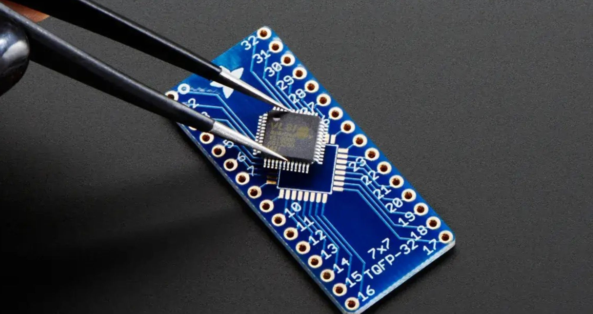

A surface-mount device (SMD) may have a very short code printed on the component’s casing. This code appears to be authoritative as it is printed on the physical casing itself; however, it is merely a single observation point from which to gather additional information. Manufacturers routinely abbreviate a lot of information such as device identity, date of manufacture, lot identification, and assembly site into a very small number of characters, and may use the same code to apply to numerous devices, regardless of their package style, pin count, function, or electrical limitations.
For background on the terminology, see this guide to component terminology. Identification of the device itself starts with separating evidence: first, the user must separate the physical observation from the evidential documentation. This first step is critical for any repair, purchasing, failure analysis, or production support. Therefore, if a match is made, even if the mechanical compatibility is established, the replacement could still be electrically wrong or belong to a different voltage, temperature range, speed, or package option. Users should focus on narrowing the possible candidates so that false certainty does not ensue from uncertainty.
Why the Same Short Marking Can Point to Different Parts
Although an abbreviated marking may be associated with an entirely different device family, the first restriction of using this abbreviated code for multiple devices is the size of the package. Many manufacturers of integrated circuits (ICs) will have multiple lines of text printed on larger packages, whereas smaller packages such as SOT-23, SC70, X2SON, or any other small package types may have room for only two to four identifying characters on their casing. Texas Instruments has explicitly documented that the detailed device information available on the small package size could be condensed into a compact code, while other traceability information may be printed on a separate line or located on the underside of the small package or on the shipping label. The exact convention is specific to a particular manufacturer and product; therefore, any generic code list cannot provide for a universal decoding facility.
This real example demonstrates just how significant the risk is of confusing these two products. onsemi produces their marking A7 for the dual switching diode BAV99L/SBAV99L in a three-terminal SOT-23 package, and Texas Instruments (TI) also lists their part marking A7 for the TPS3831G33 devices within a four-pin X2SON package. Although the description on the top of each product clearly contains identical text, it is obvious these devices are not remotely interchangeable.
- onsemi BAV99L three-terminal SOT-23 nominal package dimensions = 2.90 x 1.30 x 1.00 mm with 1.90 mm lead pitch; device code = A7; rated reverse voltage = 100 V; rated forward current = 215 mA per diode; maximum reverse recovery time = 6 ns at test conditions as defined in onsemi documentation.
- TI TPS3831G33 four-pin X2SON nominal package dimensions = 1.00 x 1.00 mm; Part marking A7; factory-trimmed threshold 3.08 V; typical supply current 150 nA; operating supply voltage range 0.9 V to 6.5 V; operating temperature range -40°C to 85°C.
Searching only for the two characters A7 within a database may find both components’ records; they would quickly be separated based on package size and terminal count. When both parts are examined in the context of their respective circuits they can be even more clearly separated; one is a dual series switching diode and the other is an ultra-low power supply voltage monitor.
What Can Be Hidden Inside a Top Marking?
The visible text in a top mark should be parsed into different fields prior to conducting any searches. Manufacturer documentation consistently illustrates how a top mark may contain both identification information and manufacturing traceability, rather than being formatted as a single continuous part number.
- Identifier: A shortened version or a code can identify a family or version, but this may not include all of the complete options for an order.
- Date: Many devices utilize a year and week system, encoded date character, or some other system used to identify the time period by the manufacturer. For example, Microchip uses YYWW in several of their label codes, where YY is the year and WW is the assembly work week.
- Lot or traceability: Microchip has several forms for lot traceability, using examples such as YYWWNNN, while other manufacturers use their own codes for lot, die run, wafer run or assembly site.
- Grade or option: A temperature grade, device revision, package options, or other variants may appear adjacent to the primary identifier.
- Orientation: A dot, notch, chamfer, bar, etc., may be used to indicate pin 1 or polarity. The meaning of any of these symbols is specific to the package and component family.
A useful example of this would be onsemi MMBT3904L. The manufacturer’s data sheet identifies 1AM as the particular device code, while showing a separate M field for the date code. The same device is an NPN transistor rated for a collector-emitter voltage of 40 V and a continuous collector current of 200 mA. If a technician were to copy every visible letter and number into a search box, as if the date character was part of the device number for the same device, the searchable strings would change from one production lot to another, even though the electrical characteristics of the device have not changed.
The marking guidance for some parts of Microchip’s SOT-23 product line separates a truncation code from date information and lot traceability.
Do not assume that every letter found on a small package represents the manufacturer part number (MPN).
Record the Evidence Before Searching
Additionally, to eliminate incorrect matches in the future, it is recommended to take a record of the facts before you search the code in a database. The most effective records will be short, easy to measure and reproducible.
- The size (dimensions) of the body: measure the length and width of the body in millimetres; if the package is similar enough to that of another outline, measure the height also, if possible.
- Terminal count and configuration: Count the number of leads or pads on the device; measure the terminal pitch where practical, determine whether the package is gull-wing or leadless, and document whether there is an exposed pad.
- Markings that are visible on the body: document line breaks, whether upper or lower case, logos, dots or bars, overlines and notches, and also any characters that may not appear to be correct. Do not change an O to a 0; do not change an I to a 1.
- The board location of the component: Record the reference designator and assembly revision. R, C, D, Q, U, and L are design conventions; none of these proves the installed MPN.
- The function of the circuit: Document where there are rails and any resistors, inductors, connectors, drivers, sensors, or controllers that are connected to the device. If the candidate requires a topology that is not found on the board, confidence should be lost.
- Document trail: use the bill of materials (BOM), schematic, assembly drawing, change history, and repair record only when they correspond to the same revision or modification state.
For production context, see SUGA’s SMT assembly services. When making identification decisions for surface-mount production, you cannot approve an exact replacement or BOM entry based on a plausible top-mark match alone.
Why a Marking Database Returns Candidates, Not Proof
When you perform a database search or query to determine markings on components, it is important to remember that the marking database is not proof of identity. The primary use of these databases is to help you find all of the possible candidates based on a known small code. When using a generic database, the entries may come from multiple manufacturers, include older parts, have different alternate packaging options, and can include records that do not have complete suffix information.
Even though you may have access to a large marking database with thousands of entries, this database cannot see the specific assembled board — its revision, pin connections — and will not be able to determine if this specific assembly has also been reworked. Therefore, it is important to use the correct sequence when attempting to determine the identity of an unknown component. For example, a broad search using the generic database may show you candidates such as BAV99 and TPS3831-family devices, but if you continue on, the next steps in the search process are to filter down those candidates to the true candidates based on physical characteristics.
Specifically, a three-terminal SOT-23 package of 2.90 x 1.30 mm cannot be the same as a four-terminal X2SON package of 1.00 x 1.00 mm. Therefore, if the device is connected across a signal path in a diode network and the connections contradict the voltage-supervisor pinout, then this candidate must be eliminated from consideration. Likewise, if the location is monitoring a power supply and there are reset-related connections, then the switching-diode candidate will also likely be implausible.
To avoid the common error of using an inexact family-level identification for ordering a precise, orderable suffix that is never seen or proven, it is best to make use of a three-level confidence model:
- Candidate: The manufacturer marking has at least one plausible entry matched to a database
- Likely family: The manufacturer marking, package, number of terminals, and circuit role agree but the exact option and traceability have not been determined
- Verified part for this assembly: The manufacturer marking convention, package, pinout, electrical role, and revision-controlled records converge to identify the same orderable part.
How to Read an Uncertain Mark Without Inventing Characters
Even though a high-resolution photo may still contain ambiguous characters, the safest way to read them is to keep the alternatives until you obtain a piece of evidence that removes those options. Some of the more commonly confused pairs are: O/0, I/1, S/5, B/8, Z/2, and G/C. There may also be issues with identifying logos or microdots as letters or punctuation.
When transcribing and interpreting a code, keep the physical orientation constant; don’t manipulate a code just because the alternate incarnation produces a known result. Use oblique light for revealing laser etching, compare multiple photographs, and take into account whether the unclear character is obscured by flux, coating, wear, or glare. If it is in the best interest of the assembly to clean, always use the manufacturer’s preferred method for cleaning the outer surface of the packaging, rather than scraping it off.
The most critical criterion for evaluating this type of identification is not the number of hits returned by a repository search; it is the number of independent constraints remaining after the evaluation of the ambiguity. For example, both O7 and 07 may return candidates; when evaluating them, do the package and pin count remain constant while the ambiguous character varies? This approach continues to control the investigation and does not allow search engines to redefine the evidence.
There Is No Universal Meaning for a Band, Dot, or Notch
An orientation mark allows one to eliminate a plausible but reversed candidate; it may also lead one to misinterpret an orientation mark transferred from one component family to another. In general, a diode band will indicate cathode orientation, while an IC dot or notch will typically indicate pin 1 for ICs. A polarized capacitor may utilize a polarity mark that is unique to that family. It is important to understand how to interpret a leadless package’s corner chamfer, dots, or molded geometry, as shown on the package drawing. An excellent illustration of this is the onsemi BAV99; in a typical SOT-23 configuration, there are three terminals.
Pin 1 is the anode, Pin 2 is the cathode, and Pin 3 is the common cathode/anode junction between the two parts of the series. In addition, the marking diagram shows A7 is the device code and M denotes the date code. Neither the device text nor the nearby microdot should be interpreted using a polarity mnemonic from an unrelated component family.
A replacement must be consistent with all four sources, which include the component family rules, the package drawing from the manufacturer, the PCB (footprint or assembly) drawing, and the circuit connections. If any of these sources do not match, then the orientation of the part is still to be determined.
When Electrical Testing Can Break a Tie
Electrical testing is more effective when the candidate list has already been narrowed down. Electrical testing includes diode mode, resistance, continuity, and controlled powered measurements to verify whether the terminal behaviour matches the proposed function. These measurements can help remove an impossible candidate from the candidate list, while a complete orderable part number cannot be guaranteed by electrical testing alone.
To clarify this concept, consider the numbers contained in both datasheets. The onsemi BAV99 has a 100 V reverse voltage rating and a maximum reverse recovery time of 6 ns at the specified testing conditions. The MMBT3904 has a 40 V collector-emitter rating, 200 mA continuous collector current rating, and 300 MHz minimum current-gain bandwidth product, all measured under the specified conditions. Despite its ability to help distinguish between the junction behaviour of a diode and transistor, a multimeter cannot be relied upon to verify the ratings, speed specifications, temperature ratings or unprinted suffixes of these items.
The process of taking measurements in-circuit is further complicated by the presence of parallel paths in the circuit. For a resistance measurement, the readings taken may also include bias resistors or other semiconductor junctions as well as, in some cases, inductor windings or protection networks.
When taking this type of reading in-circuit, it is important to view the measurement as evidence of the circuit’s operation and not as a “magic” identity test. If you are required to isolate the component from the circuit, you must follow the approved repair practices and board safety procedures, instead of simply lifting the terminals and taking a guess.
Worked Example: One A7 Mark, Two Completely Different Devices
If you identify that an unknown device is marked A7, a search for the code alone will not allow you to differentiate between the two manufacturers’ documented options for the A7 mark, such as the BAV99 dual switching diode manufactured by ON Semiconductor and the TPS3831G33 voltage supervisor manufactured by Texas Instruments.
The first step in identifying which type of A7 device you have is to take an inventory of the number of terminals on the device and the size of the device. Both of these measurements are structurally unique to the two candidates and as such should provide sufficient information to eliminate one of the candidates from consideration; agreement with the marking and circuit role is also needed to reach likely family in the confidence model.
The second step is to compare the specific circuit roles of the devices using the candidate datasheets. A location wired as a switching or clamp diode network supports one hypothesis; a location monitoring a supply rail with a reset connection supports the other.
Third, confirm the ratings only after the function already fits, and check that they belong to the hypothesized device type at all. A diode’s reverse-voltage rating has no counterpart on a supervisor’s datasheet, and a supervisor’s threshold voltage has no counterpart on a diode’s.
Finally, check the revision-controlled BOM or schematic. If the approved record names the same manufacturer part whose package, pinout, marking, and function have already matched, the evidence converges to the verified-part level. If those records are missing, the conclusion can still be strong at the family level, but the exact original MPN should remain qualified.
A Second Example: Separate the Device Code From the Date Code
Now consider a three-terminal SOT-23 marked with 1AM plus an additional M-style date position – the same device identified earlier as onsemi’s MMBT3904L, where 1AM is the device code and the M field carries date information.
The package must conform to the SOT-23 package form factor and the specific pinout as previously published for the device. The surrounding circuit connections must be consistent with the candidate’s NPN pinout and electrical characteristics. When the package, pinout, and circuit function are consistent, 1AM is considered strong supporting identity evidence, because the date character associated with 1AM never has to be the same as that of a different production lot; the same device identity remains constant, but the date character may vary between production lots.
The distinction between device codes and date codes also provides an explanation as to why photographs of two assemblies may show different additional characters even though the functional component is unchanged. A changed date or lot field is a normal use of traceability variation; a changed device identifier, package identifier, pin mapping, or grade identifier may not be a normal usage of traceability variation.
When the Evidence Is Still Not Enough
Stop if there is conflicting independent evidence. A brief code may match; however, the terminal count does not. The physical dimensions of the package may match; however, the pin mapping may contradict the PCB connections. The specification for the device describes the same function, but may not match the voltage or temperature information. The BOM may not match the physical assembly due to repair or revision changes after the fact.
When in doubt, use the most specific conclusion supported by the evidence. The supported conclusion may be that the part can be directly ordered, that the part belongs to a likely family of devices, that the part belongs to a probable functional classification, or simply that there is still an unresolved part with two remaining candidates. As documented uncertainty is always more useful than fabricated precision, documenting uncertainty is an essential key to making accurate buying/purchasing and production decisions.
A good identification record should allow another engineer to replicate the conclusion based on the same mark, dimensions, pin configurations, circuit connections, manufacturer documentation, and revision-controlled records. If another engineer is not able to replicate the conclusion based on these criteria, the marking on the device has allowed for narrowing the search, but has not yet completed it.